C*: pitch
Sun 07 September 2014
The axes is the most documented one. Maybe because it is the less easy to understand. Of course other post will consider the two other axes.
The complication arise when thinking of what can be controlled:
- the plane's stability (called "assiette" in french) and therefore the pitch rate.
- the angle of attack (usually noted \(\alpha\))
- the load factor (usually noted \(n\))
overall process
Overall chain
I don't know all the name of the transformation process, I don't even know how accurate this is, the scheme does not necessarily respect the feed-back design rules, but to me it is understandable and coherent, and I hope by the average reader of this blog can understand it and discuss the limitations and potential errors.
Details
Let's detail the boxes:
Foo
inputs:
- flight control position
output:
- pitch moment
The position of flight control surface provide an aerodynamic force on the airplane (upward or downward), resulting in a pitch momentum (all acts as if the airplane rotate around its gravity center), and then a pitch rate. Note that this force varies depending on multiple factors (the angle of attack, the air density, the airspeed,...)
Simple integration law
inputs:
- pitch moment
output:
- pitch
It is just a consequence of classical mechanics rules.
Lift curve
Lift coefficient curve (Photo credit: Wikipedia)
Input are:
- angle of attack \(\alpha\)
- speed \(V_x\)
Output are:
- lift
The more you increase the angle of attack, the more you increase the lift (and the drag). The more you increase the speed, the more you increase the lift (and also a little the drag). Given a speed, the variation of lift depending on the angle of attack is called the lift coefficient curve. Note that it is valid for a certain range of angle of attack. If the angle is too high, the aircraft stall, it the angle is too low, the aircraft fall. In both cases, the aricraft cannot fly correctly.
In normal operation, this angle is in the part of the curve where lift increase whane the angle increase.
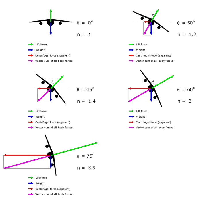
load factor
[caption id="" align="alignright" width="350"] Load factor n as a function of its angle of bank θ (Photo credit: Wikipedia)[/caption]
input are:
- lift (\(L\))
the output are
- load factor (\(n\))
both are proportionnal. (\(n=\frac{L}{W}\) where \(W\) represent the weight).
Bar
inputs:
- pitch
output:
- angle of attack \(\alpha\)
This is easy to understand: the pitch is the angle between a frame of reference (usually the Earth and therefore the horizon) and the longitudinal axes of the plane, the angle of attack is the angle between the airflow (trajectory in a frame of reference linked to the air) and the wings chord (more or less parallel to the longitudinal axe of the plane), and b
command
The physical value commanded is the load factor. It does not seem natural but is logical. If no command is apply (command at neutral position), the pilot expect its plane to fly straight forward, i.e. its trajectory to be not altered, i.e. the load factor to be equal to 1.
Note that form one constructor to another, this input vary[1. see some archive at flightglobal]. The pilot may command a combination of pitch rate and load factor.
All those variation will be discussed later as I'm scheduling a post about flight control mode (what happen when all the condition to operate normal law are not met).
limits
The overall scheme present some feedback whose existence is not trivial. This is done to limit physical values to acceptable ranges. This means that if the computer will act to stay within this limits even if the pilots instruction disagree.
The pitch limitation is used to stay in comfortable values and to stay in flyable condition even if case of spatial desorientation.
The angle of attack limitation prevent from stalling.
corrections
Moreover, you must consider the non-standard cases when it is difficult to say the lift is considered vertical, e.g. when the plane is not quite horizontal (bank angle not null, plane climbing or descending) in which cases the values such as load factor must be corrected or when some physical values cannot be maintained into defined limits (e.g. going from a powerfull vertical draft to another)
Related articles (or not):
